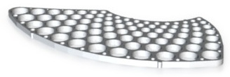
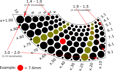
Below is the key for the Metric Hole Test Pattern object, which is available at Shapeways.com. It is a flat, 3 millimeter thick piece with standard metric drill bit size holes, and can be used just as a decoration, or to measure detail, accuracy, and distortion (holes and flatness) in printed materials. It’s also useful for judging the printed sizes of clearance or tap holes, or choosing a hole size to match a part you already have.
Holes range in size from 1mm to 3mm in 0.1mm steps, and from 3mm to 10mm in both 0.1mm steps and 0.25mm steps.

The holes organized in “rows” and placed as efficiently as possible in order to limit material use. This results in a unique and beautiful shape. There are also small bumps on the edges to indicate the odd (x.25 and x.75) measurements. It is 3mm thick so that it can be printed with a variety of materials, including stainless steel.

It was a bit of a challenge figuring out the ideal hole placements…

cool – you’re right it is a cool looking design.
I really like the design, however I am wondering how to produce it. CNC milling in aluminium with 0.05mm accuracy is a challenge, although possible. However, 3d printing? In my experience, the surface roughness of shapeways is already larger than 0.1, and it wouldn’t last very long?
Or are there some neat tricks to overcome this.
Hello Bernhard. Thanks for your comments!
I pretty sure that milling would be probably get you the best results, but I have only ever 3D printed this. (It’s certainly not perfect, especially with a 0.5mm nozzle.) Every kind of 3D printing I’ve ever tried will likely leave some of the smaller holes filled in, and so at least those would need to be drilled out — and possibly others if you want to use it as a gauge. For example, if you take a look at my stainless steel detail test at http://www.thefrankes.com/wp/?p=2138, you can see that the effective resolution for holes is somewhere between 0.4mm and 0.6mm for that material.