A couple of people have noticed this, so I thought I’d write it up. There’s nothing wrong — it’s just something to be aware of if you’re soldering up a Sanguinololu 1.3a PCB.
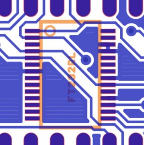
If you look closely at the circuit board where the FTDI chip goes, you’ll notice a tiny solder bridge between pins 25 and 26 (below the “L” in “FT232RL”). I noticed it when I first inspected the board, and I looked at the original gerber files to make sure it was part of the design. It is, in fact, part of the original design (see photo below), so there’s no need to try to remove it. (To confuse the issue, the instructions even say to look for things like this.)
If you did remove it, that’s okay, too — those pins (which both go to ground) are still connected inside of the outline of the chip.
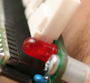
One other thing to note is that the pin headers along the top of the board sit a little further in than those along the other sides. This is also exactly as it is in the original gerber files, but it means that the PCB might prevent some right-angle headers (like those in the Mouser project kit) from plugging all the way in unless the male headers are soldered a little high. (See the second photo.) This is probably more of an aesthetic issue than a functional one, but if you want to make sure they plug in completely, you can use one of the female connectors to space it properly when you solder it on.


